Rules
2025 DENVER GINGERBREAD BRIDGE RULES
Bridge Constraints:
- No bridge may exceed 12” tall or 6” in width. The 12” dimension is an overall dimension; this is measured from the lowest point to the tallest point just prior to being put in the test rig.
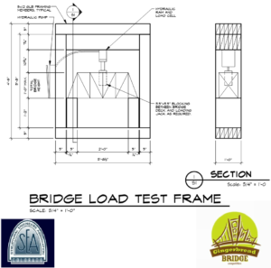
- Bridges must span a minimum of 24” between supports. The maximum bridge length is 33”. See Bridge Load Test Frame for test rig layout.
- Bridges may not be solid (one member) in cross-section. They may be multiple ply adhered members in either direction so long as each panel complies with maximum panel dimensions. Teams may not cast elements in a mold or dip their bridges in candy. See Photo 1 for an example of a bridge that is not compliant with this rule. This photo is near the end of this page. Scroll down to view.
- Structural Panel Members:
- Structural panels must be made only from baked gingerbread or graham crackers. Each panel cannot be larger than 8 inches long, 4 inches wide, and ¾ inch thick. Panels may be glued together to make bigger pieces, but every panel must stay within the size limits. All main bridge parts that hold weight (compression members) must be made from gingerbread or graham cracker panels. Panels made by crushing gingerbread and mixing it with melted candy or sugar are not allowed, and panels cannot be cast in molds from candy, sugar, or chocolate. See Photo 2 for an example utilizing combined panels to form larger members. This photo is near the end of this page. Scroll down to view.
- Tension Members and Connections:
- Candy or sugar can be used only for parts that pull (tension members, such as cables) or for connection pieces (such as bolts, welds, or gussets). These candy or sugar parts cannot be used for compression members or for any part that holds weight by pushing. I.e.: Icing may be used as glue for connections only.
- The bridge must fit within the test rig as shown. See bottom of rules for diagram of Bridge Load Test Frame.
- Bridge ends MAY NOT be laterally braced by test rig vertical legs (i.e. no thrusting).
- The bridge’s deck must accommodate the loading mechanism/applicator (RE: loading procedure). You are solely responsible for ensuring the compatibility of your bridge with the loading mechanism.
- The bridge will have to support any wood spacers required to bring the ram into contact with the bridge prior to testing.
- Bridges must be self-supporting to earn a strength to weight ratio. Bridges failing before loading begins will receive a Failure Load = 0 lbs.
- Candy decorations may be added, but may not be load bearing or structural (cables and connections exempt).
- The “eat your own bridge” policy will be enforced! Reasonable portions of your bridge will be chosen for you to consume.
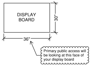
Architectural Display Constraints:
- The maximum size of the architectural display is 36″ long x 30″ deep. Primary public access will be along the long dimension of the display board. See display board figure below for additional information.
- All display components must be edible with the exception of 30” x 36” display board.
- A non-edible poster backdrop may be used. Backdrop width should not exceed maximum display length. Any posters or backdrops must be self-supporting.
- The bridge may have removable “architectural components” that will not be part of the bridge structure to be tested.
Loading Procedure:
- The bridge weight will be determined by weighing it on a digital scale.
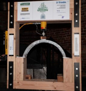
- Bridge contestants will place their bridge in the loading device with review by Test Monitors. Plastic bags of flour will be available to help support the bridge evenly over the bearing area.
- All bridges must be able to support a 3.5” x 3.5” square load applicator. Structural or non-structural portions of the bridge that cannot accommodate the test apparatus loading mechanism may suffer damage prior to loading.
- A contestant from the team whose bridge is being tested will apply the load to the bridge (via the hydraulic ram) until failure occurs.
- If the bridge capacity exceeds the loading ability of the test rig, its rating will be based upon its maximum test load as measured divided by its weight.
If you have any concerns about your bridge’s compatibility with either the rules or loading device, please do not hesitate to contact the YMG Committee by emailing ymg@seacolorado.org!
LOADING MECHANISM WEIGHTS:
Spacer Blocks:
4x4x1′-0″ = 2.2lbs
4x4x0′-9″ = 1.7lbs
4x4x0′-6″ = 1.0lbs
4x4x0′-3″ = 0.5lbs
4x4x0′-1 1/4″ = 0.3lbs
4x4x0′-1 1/8″ = 0.2lbs
1x6x0′-5 3/4″ = 0.4lbs
Leveling Bags:
0.2-0.3lbs each

Photo 1: Example of non-compliant bridge utilizing cast-in/precast members for non-tension only members.

Photo 2: Example of bridge utilizing individual connected panels to form larger members in accordance with Rule #3.